There’s all sorts of arguments on the internet on whether you can use a Passive DI in reverse as a Reamp, or go straight out of your amp or maybe use a special cable?
What IS Reamping? What are these things you do it with? Why do you use them? And can you really do that?
Let’s find out with some measurements and then real world tests.
THIS IS A MEDIA HEAVY POST!!!!!!!
This post will load up to 105mb of data!!!
This post will load up to 105mb of data!!!
This post will load up to 105mb of data!!!
This post will load up to 105mb of data!!!
This post will load up to 105mb of data!!!
There’s also another 97.4mb of optional downloads.
Contents
- THIS IS A MEDIA HEAVY POST!!!!!!!
- Legend
- Equipment
- Test Files
- Impedance
- Introduction to direct boxes
- Introduction to Reamping
- Reamp with a direct box? What’s the problem?
- Testing
- Real sounds
- H-Pad
- How do I do this?
- Conclusion
- Support Me!
Legend
Some terms:
- DI - Direct box run in reverse.
- H-pad - A resistor network built into the cable to reduce the signal level.
- I will be using an H-pad with 4 resistors of 270Ω and a single 47Ω resistor.
- H-pad + pad means that I use the the H-Pad cable along with the Pad on the Radial JDI direct box.
- Reamp - A box specifically made to convert an line level signal to something that can be sent to a guitar amp.
- Pad - A circuit that reduces the signal level. My JDI has a 15dB pad.
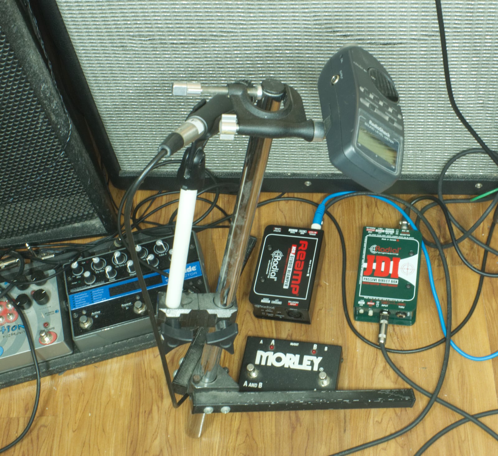
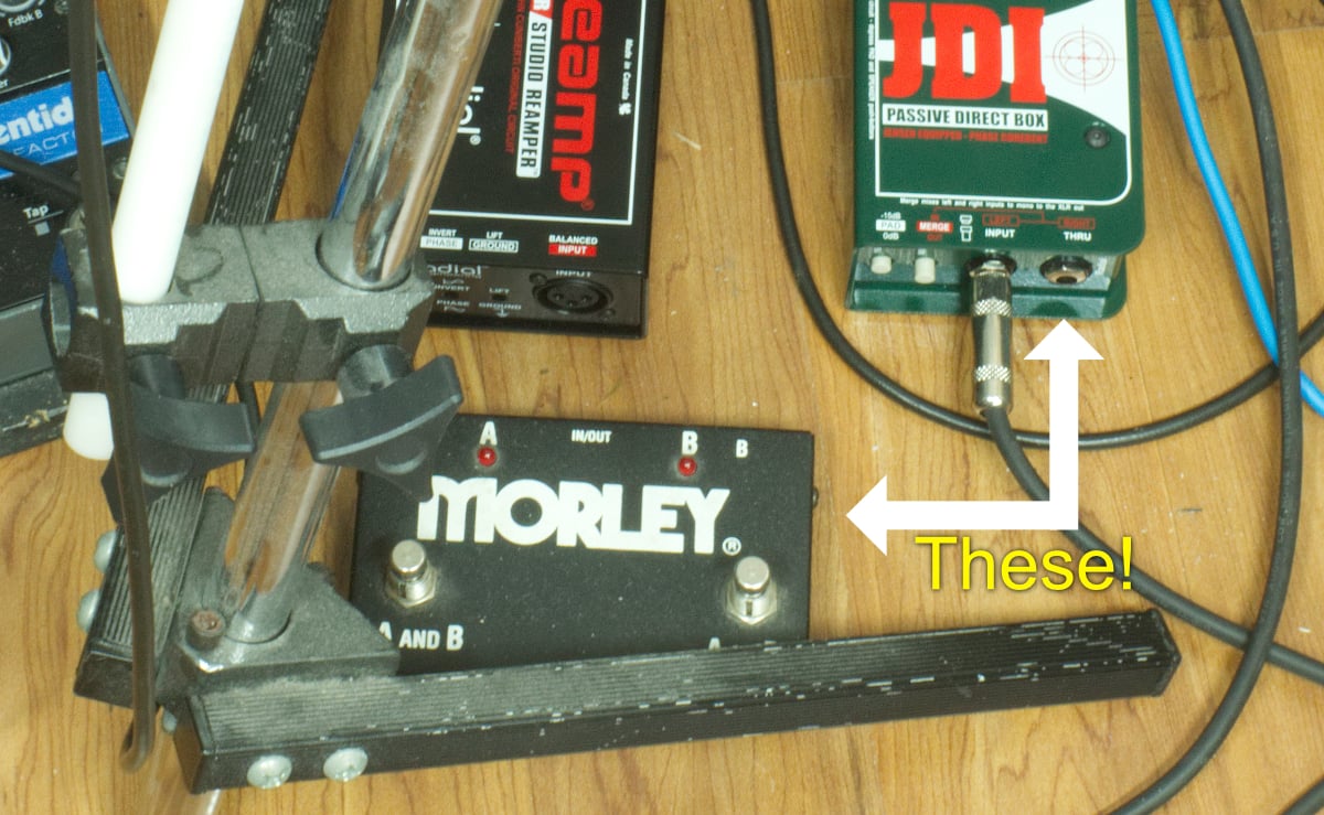
Equipment
The following pieces of equipment will be used for demonstration:
- Radial JDI passive direct box
- Radial JCR passive Reamp
- Focusrite Clarett 8PreX
- Fender Hotrod Deville 410 that’s been heavily modified. It’s my favorite amp.
Cabling is Belden.
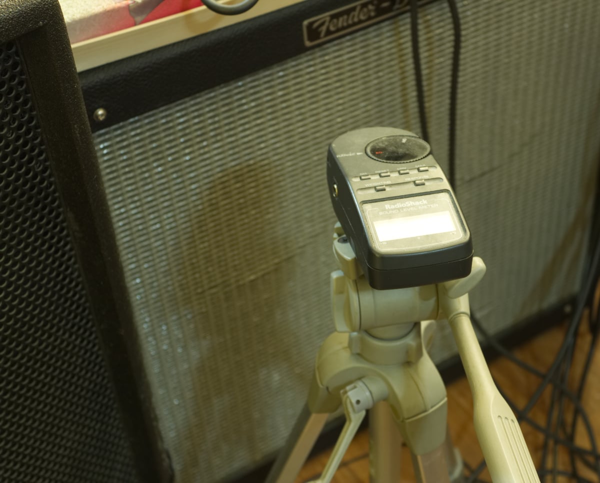
I will be primarily using MNoiseGenerator with pink noise then REW and Span Plus for signal measurements.
I’m using an old (and reliable) Radioshack SPL meter.
Test Files
Here’s the CSF files for use with Voxengo Span Plus. These are the results for the Distortion sections. 18.5mb
Here’s the REW test files for use with REW. These are the test results for the Frequency and part of the Distortion sections. 78.9mb
Impedance
Before we start there’s a concept that needs to be clarified or some of the side-effects that we see happening later won’t make any sense.
Impedance.
Electrical impedance, not the software development type (which is surprisingly similar!)
Electrical resistance is pretty easy to grok. It resists electrical current’s flow. The concept of resisting current flow show be pretty easy to imagine even if you have no concept of electricity at all.
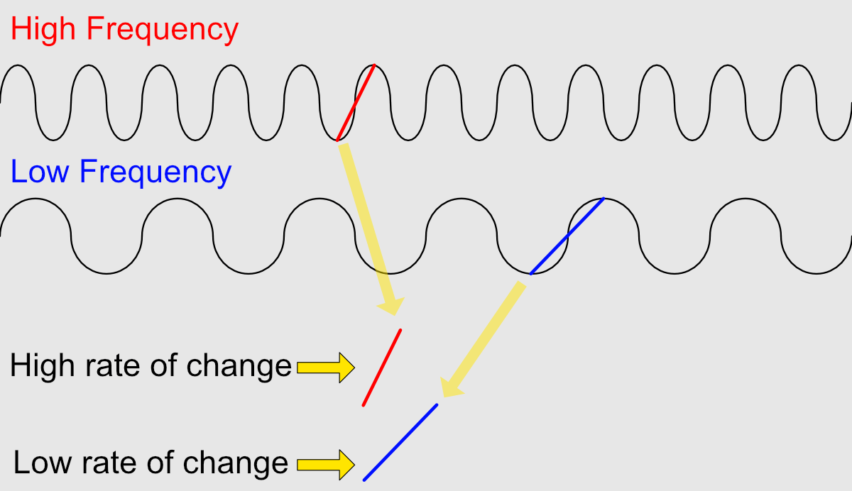
Impedance is difference. It’s the resistance to change when there’s an alternating current. The rate of change of the current is what we generally call the frequency of change or just frequency.
In the graphic above you can see the difference. When we have a high frequency signal, the rate of change is high. The slope from -1 to the next +1 in the sine is a steep line.
With a low frequency signal the rate of change is lower. The line from -1 to +1 has a lower slope.
Since our musical signals have a complex set of sines (see this post for more), there are complex interactions with the impedance of the circuit. If the impedance is mis-matched then there will be a difference in how much “resistance” exists between low frequency and high frequency signals.
So that will mean that impedance mismatches may end up causing changes in frequency response.
Introduction to direct boxes
Guitars have a low voltage output and very high impedance (resistance to rate of change in AC current). We can assume an average of about -20dBu for a guitar output. Guitar amps expect a signal that conforms to these requirements.
Microphone inputs expect low voltage and low impedance. Microphones will generally output around -30dBu, so the voltage is lower than the guitar.
To properly interface a guitar with a microphone pre-amp, we need to go from high-impedance to low-impedance and high voltage to lower voltage. This is the job of a Direct Box.
It uses a step down transformer to get this impedance transformation that we require and stepping down the voltage a bit as well. When using transformers to step down the voltage, we also step down the impedance. So we can go from high-impedance and higher voltage to low-impedance and lower voltage at the same time. Perfect!
NOTES
Sometimes there will be some (optional?) resistive components to also lower the level, and perhaps some other features.
This all gets rather fuzzy because guitar pickups (especially) and microphone pre-amps vary significantly. So that’s why we need to test!
There’s also other benefits to using a DI in stage environments (going from long unbalance cable runs to long balanced cable runs), that I won’t be discussing.
Introduction to Reamping
Re-amping is the reverse, sorta.
Line outputs, from your mixer or audio interface, are low impedance and high voltage.
A reamp lets us do that. It’s designed to take a 600Ω impedance and 0dBv(2.21dBU) signal and turn it into a 200k-1mΩ and -20dBu signal.
Reamp with a direct box? What’s the problem?
So you may think, OK! I will take my direct box, and run it in reverse! This got me from guitar to interface, so it surely can get me from interface to guitar amp… right?
Well. Maybe.
The direct box is designed to take a signal from 200k to 1mΩ impedance and -20dBu and change it to ~1.5kΩ impedance and ~-30dBu. Our line output is 600Ω and 0dBu. So we’re running a much hotter signal IN than we were expecting to put OUT. This is important when we run it in reverse. Many people don’t understand that guitars put out a hotter signal than microphones and a DI-box reduces the level (and the impedance).
So let’s think about this like math.
Let’s assume our DI box ‘run forward’ (the normal way) is stepping down a ratio of 4:1. So in terms of voltage that’s about -12dB. We were trying to go from a -20dBu guitar signal to something expecting a -30dBu microphone signal, and the -12dBu gives us -32dBu. Quite nice.
If we run it in reverse, we’re increasing our voltage by 1:4. That once again gives us +12dB. BUT line outputs, like on our audio interface, are outputting +2.21dBu already! That means that the revers DI box is increasing the level to +14.21dBu! Our amp is expecting around -20dBu. That’s not good. We’re abut 34dB off! We have the impedance close to what we want, but our signal level is massively FUBAR.
So you can drop the output from your interface to compensate, but no matter how much you turn down your digital signal the analog output has a fixed noise floor. That means that we can lower our signal -34dB, but our noise floor doesn’t move. Effectively we’re increasing our signal to noise ratio by -34dB.
An alternative is to use an analog ‘pad’ to reduce the signal level. A common type is called an H-pad, but generally a T-pad is more appropriate in this case (fewer components used, less space needed). I’ll be teaching you to use an H-pad because it’s more useful in general and if you only need to know one pad type… that’s it.
NOTE None of these values are from real devices. Just some easy to use values for explanation.
Testing
Testing Levels
For SPL measurements I used Pink Noise at -20dbFS RMS. For voltage measurements I used 100hz, 1,000 and 10,000hz signals at -20dBFS (peak) direct to an oscilloscope. These 3 signals will give you a very general idea of the measurement setup via 3 point frequency spectrum.
I tested both the output voltage and SPL (C-Weighted, slow) through an amp at a fixed setting of the following setups:
- Interface Output
- 100hz - 310mv
- 1,000hz - 320mv
- 10,000hz - 420mv
- Pink Noise - 86dB SPLc
- Passive DI
- 100hz - 3.54v
- 1,000hz - 3.6v
- 10,000hz - 6v
- Pink Noise - 108dB SPLc
- Passive DI -15dB pad onboard
- 100hz - 160mv
- 1,000hz - 180mv
- 10,000hz - 205mv
- Pink Noise - 80dB SPLc
- Passive DI with 270Ω/47Ω H-Pad cable
- 100hz - 458mv
- 1,000hz - 430mv
- 10,000hz - 215mv
- Pink Noise - 87db SPLc
- Passive DI -15dB pad onboard with 270Ω/47Ω H-Pad cable -
- 100hz - 15mv
- 1,000hz - 13.5mv
- 10,000hz - 14.5mv
- Pink Noise - 52dB SPLc
- Reamp 50% -
- 100hz - 55mv
- 1,000hz - 58mv
- 10,000hz - 67mv
- Pink Noise - 78dB SPLc
- Reamp 75% -
- 100hz - 300mv
- 1,000hz - 325mv
- 10,000hz - 360mv
- Pink Noise - 93dB SPLc
- Reamp 100% -
- 100hz - 402mv
- 1,000hz - 435mv
- 10,000hz - 480mv
- PinkNoise - 97dB SPLc
- For fun - Guitar strumming an Am chord
- 80-100mv - not remotely reliable.
- 90dB SPLc
Discussion
I’m glad I wore ear protection. The Passive DI reversed by itself was far, far too loud, as expected of course.
These values only matter relative to each other, so take note of how “loud” or “strong” the signal levels are relative to each other. Particularly note the DI box run in reverse, which is incredibly “loud” like we expected!
Noise
I have set up two different sources for noise: no output and a recording of a guitar making no sound.
To do this I first calibrate a 200hz sine wave through the guitar amp to 90db SPLc. Then I measure the noise level.
The goal of this test is to see what the noise floor is when the guitar amp is outputting the same level signal.
- Amp base noise
- No connection - 58dB SPLc
- Interface Output - Sine at -44.1dBFS
- No output - 59dB SPLc
- Guitar recording - 60dB SPLc
- Passive DI - Sine at -64.1dBFS
- No output - 59dB SPLc
- Guitar recording - 66dB SPLc
- Passive DI -15dB pad onboard - Sine at -37.8dBFS
- No output - 59dB SPLc
- Guitar recording - 60dB SPLc
- Passive DI with 270Ω/47Ω H-Pad cable - Sine at -48.8dBFS
- No output - 59dB SPLc
- Guitar recording - 60dB SPLc
- Passive DI -15dB pad onboard with 270Ω/47Ω H-Pad cable - Sine at -11.0dBFS
- No output - 59dB SPLc
- Guitar recording - 60dB SPLc
- Reamp 50% - Sine at -29dBFS
- No output - 59dB SPLc
- Guitar recording - 60dB SPLc
- Reamp 75% - Sine at -44.4dBFS
- No output - 59dB SPLc
- Guitar recording - 60dB SPLc
- Reamp 100% - Sine at -46.9dBFS
- No output - 59dB SPLc
- Guitar recording - 59dB SPLc
Discussion
One major of note here is that using a passive DI such as the Radial JDI is not ideal. It’s the only example that exhibits an amplification of the guitar recording noise beyond the self noise of the amplifier.
These results can be interpreted in two ways:
- We can say for certain that with this setup, at no point does adjusting the output signal (digitally) increase the noise beyond the self-noise of the amp. I did some rough calculations, and I would need a guitar amp with a self-noise of -100dB or so for adjusting the digital gain to become a problem. That’s fairly common for hi-fi amplifiers, let alone for guitar amplifiers.
- All of these set ups are capable of producing an output level that is satisfactory for the amplifier to produce a guitar sound with a distortion level that’s in line with what we want.
Lost Bits
I’ve seen this ridiculous notion that in some cases you ‘lose bits’ if you turn down the signal level in the DAW. NO.NO.NO.NO. You gain noise. Bit depth defines the noise floor for a digital signal, nothing else!
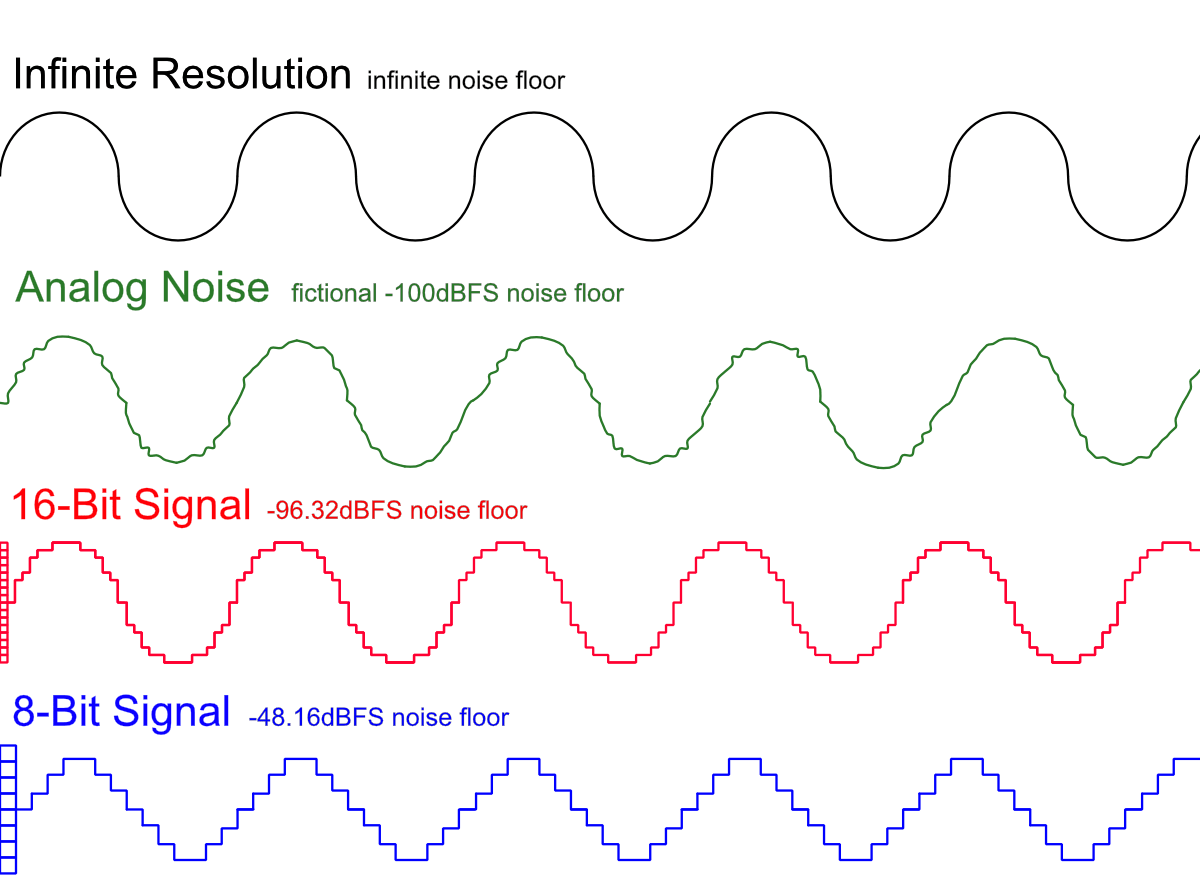
The graphic above demonstrates this visually.
- With infinite resolution and a single sine wave we have no noise. It’s a perfect signal.
- -100db analog noise floor gives us some squiggles along our waveform. (Pardon my physically impossible drawing with time travel.)
- 16-bit signal gives us ~-96dBFS noise floor, and we’re much ‘squigglier’
- 8-bit signal gives us a terrible ~-48dbFS noise floor… and the waveform is quite destructed.
That’s just noise though. It’s quantization noise, but it’s only noise. The only information that’s “lost” is the information below the noise floor.
Let’s try this with real signals:
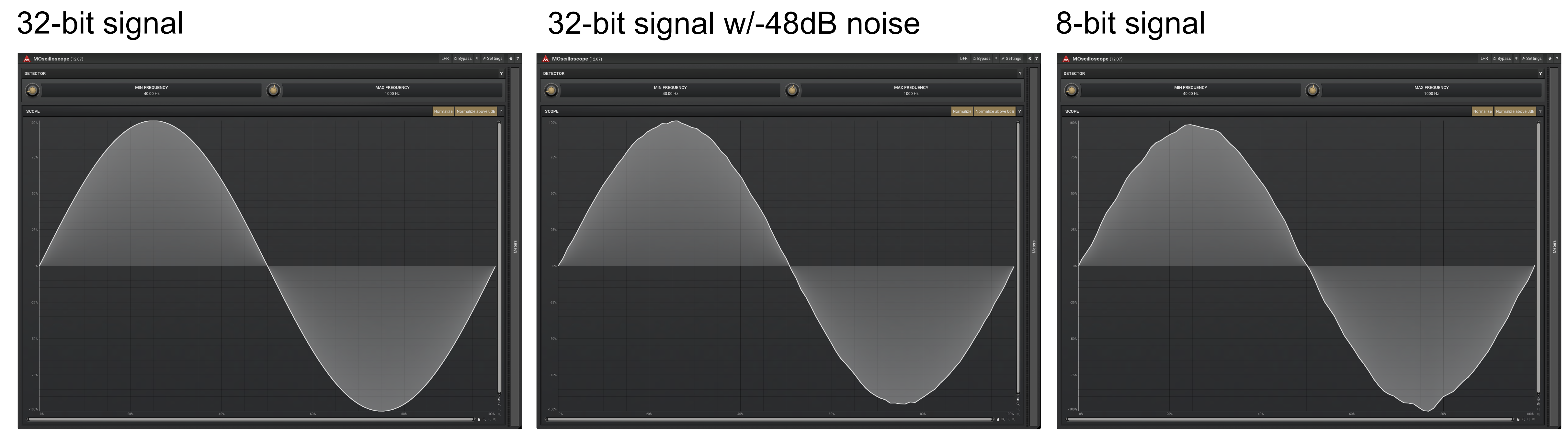
Above is a 32-bit floating point sine wave with a ridiculously low noise floor, a 32-bit floating point signal with -48dBFS of pink noise added and an 8-bit sine wave.
The last two look a lot a like don’t they?
That’s because they are a lot a like! The noise sounds different, but the only “loss of information” is that which is masked by the noise floor.
So when we’re looking into this Reamping business from a digital perspective, we can evaluate it purely from a noise perspective.
We do need to watch (and listen) and see if changing the digital gain increases our noise. If that occurs then we know that our noise source is quantization noise instead of an analog sourced noise. That could be a potential source of the sound changing.
It’s important to recognize though that we don’t ‘lose bits’. We only lose information when our digital noise floor exceeds our analog noise floor. Thusfar in the testing that has not happened (and will not happen!)
So before you go thinking that we’ve “lost information” by adjusting the signal level in the DAW, I suggest you go back to the noise section and look at those results. You’d need a really hi-fi guitar amp before you’d start hearing noise from lowering the level in your DAW in most cases!
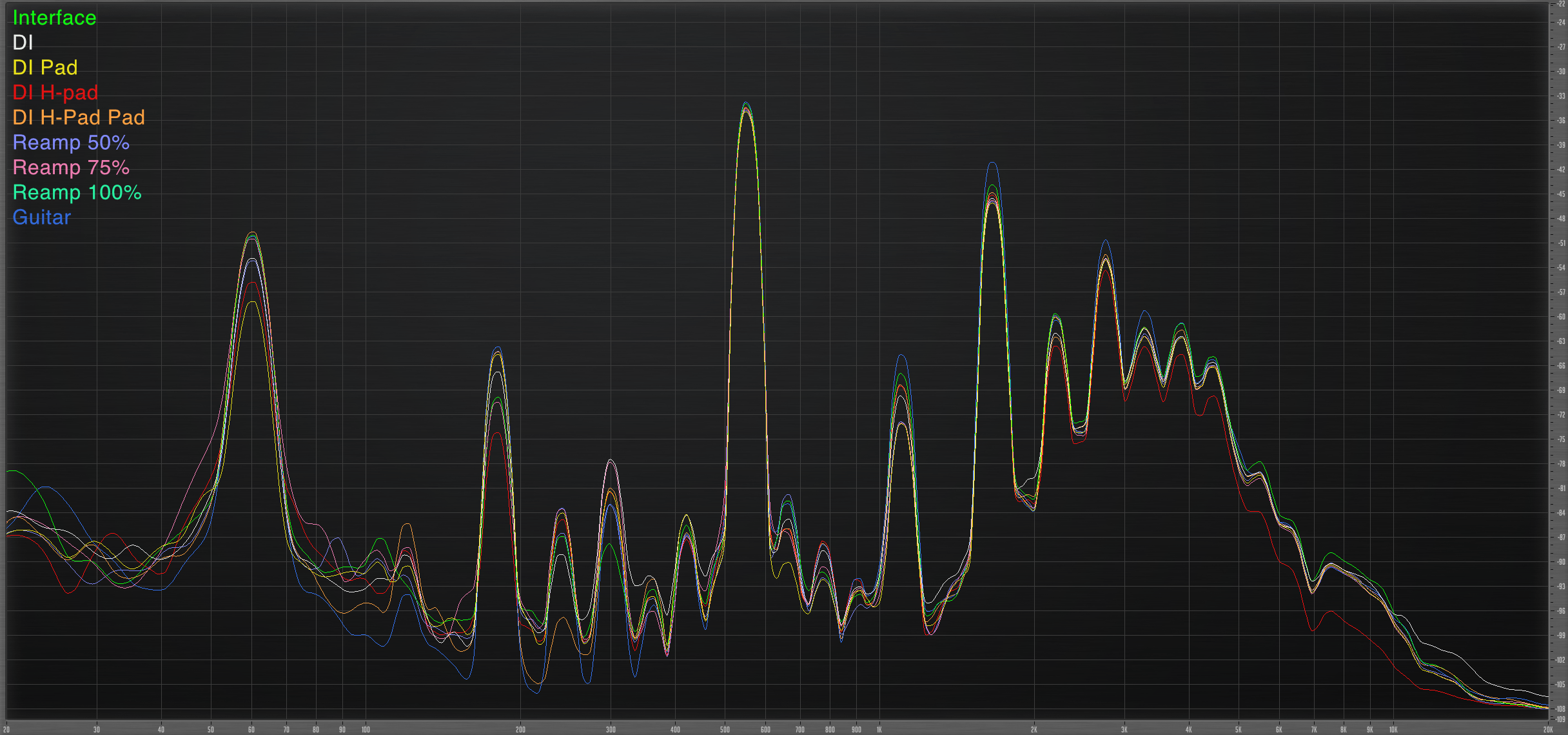
Frequency
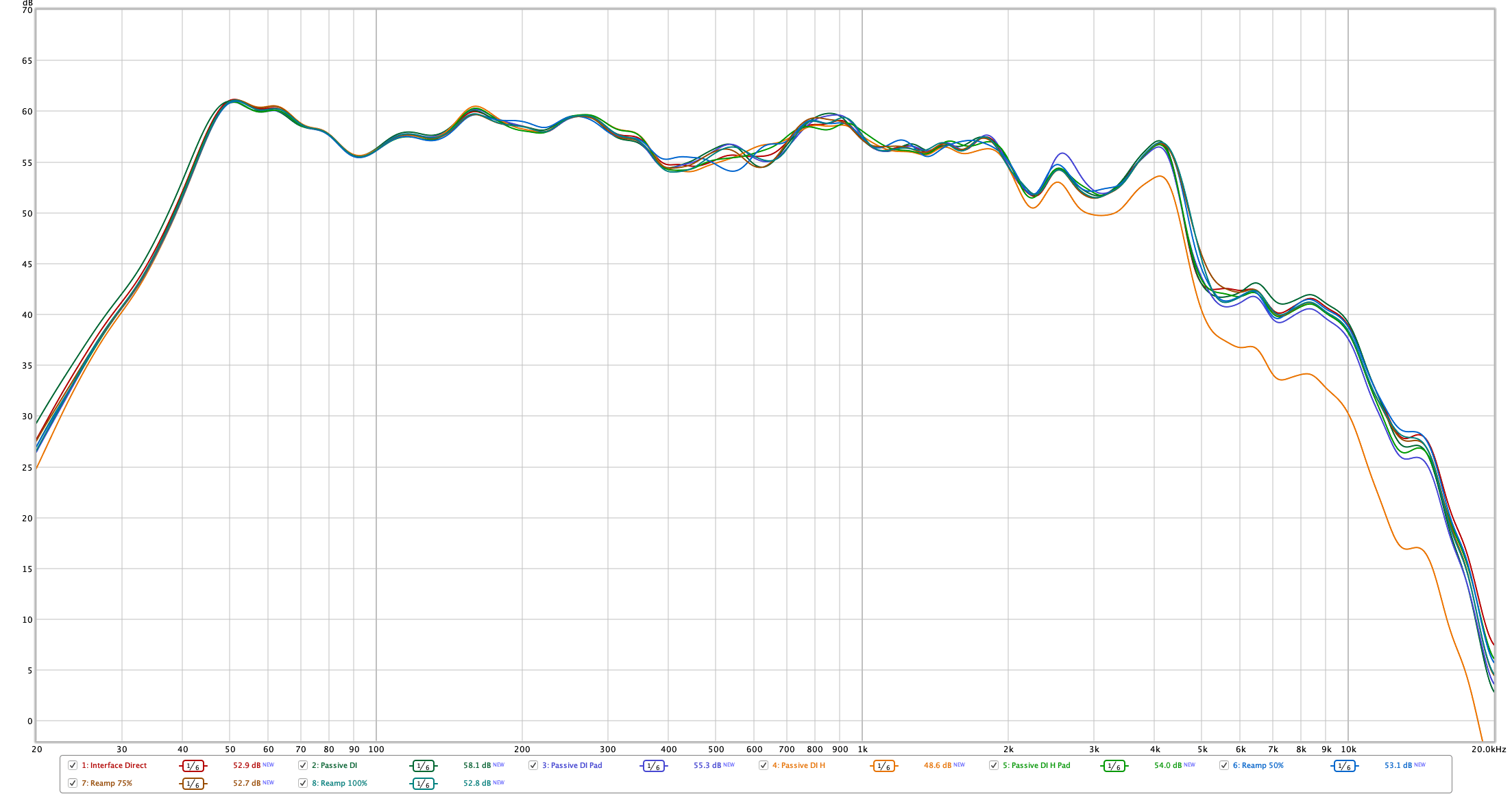
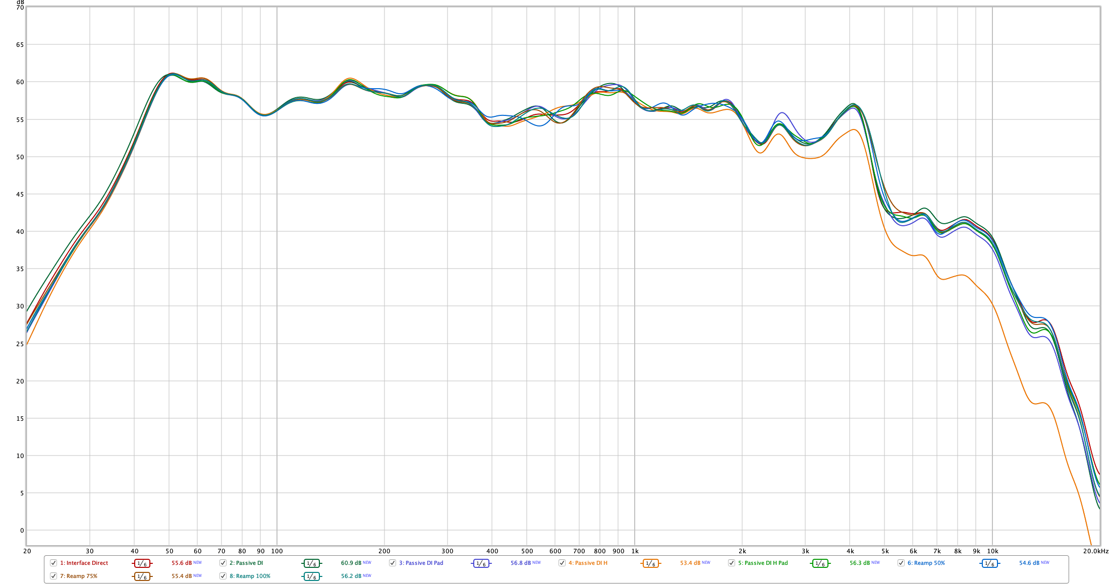
Now that we know noise is not a major concern we can look and see if impedance mismatches are going to cause frequency issues.
I use the previous values determined in the noise section to ensure that the sweeps done are all at the same in room volume. The tests were recorded with a ECM8000 2ft away from the amplifier and compensated calibration.
The only thing that matters here is the relative measurements, not the absolute measurements.
The measurement software I use only lets me use signals down to -59.9dBFS. So the -64.1dBFS compensation for the passive DI was not possible. I adjusted this in the measurements themselves (since we’re not comparing noise here, it’s irrelevant).
All of the measurement files are here so you can load them and look for yourself in REQW.
Discussion
So what do we get from this? All of these methods are fine for the most part. Using the Passive DI + H-pad has a light high frequency rolloff, while the h-pad + DI pad does not. I don’t actually understand why that is at all. It would almost make sense, except that Passive DI + Pad + H-pad is fine!
However it’s very clear that with the level calibrated correctly there is almost zero difference. The biggest differences (ignoring the H-pad) is between the Passive DI and Passive DI + Pad at 13.5khz. The difference is about 3dB, but this is a range where there is often very little audible information. It certainly could make a difference in some very high gain situations with high-fidelity speakers.
Distortion
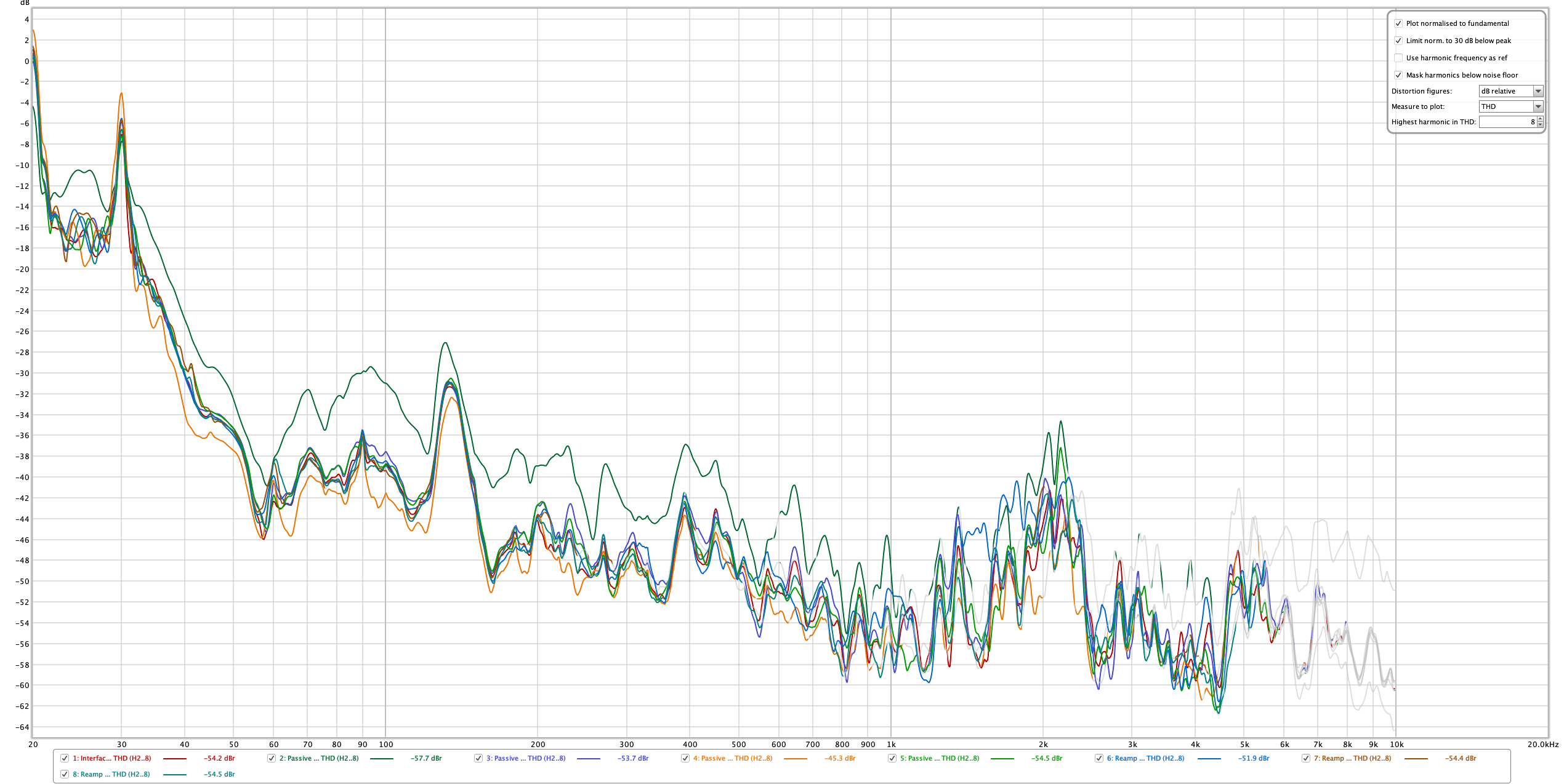
This time I’m measuring the distortion.
- THD - The THD (total harmonic distortion) plot shows that the measurements are quite close. +/- 1.2dB. This is taken from the previous measurements (using the same data). I know the legend is messed up, but I can’t fix it. The rogue line is the Passive DI reversed.
- Distortion - This is a 200hz Sine wave with the digital output adjusted until the input signal measured -20dBFS.
Discussion
In the second plot we can see some fairly major differences in the 4th harmonic (1khz). There’s up to a 4.5dB difference. This appears to be the H-Pad mostly. THe H-pad alone was already known to have issues so this isn’t surprising to me.
The H-Pad acts pretty oddly in all of these tests, but the differences are still relatively minor. 4.5dB is certainly a large change, but in my experience very few people can hear a 4.5dB 4th harmonic change in a complex signal. (I did check! Nobody could hear the difference.)
That said… there is a difference.
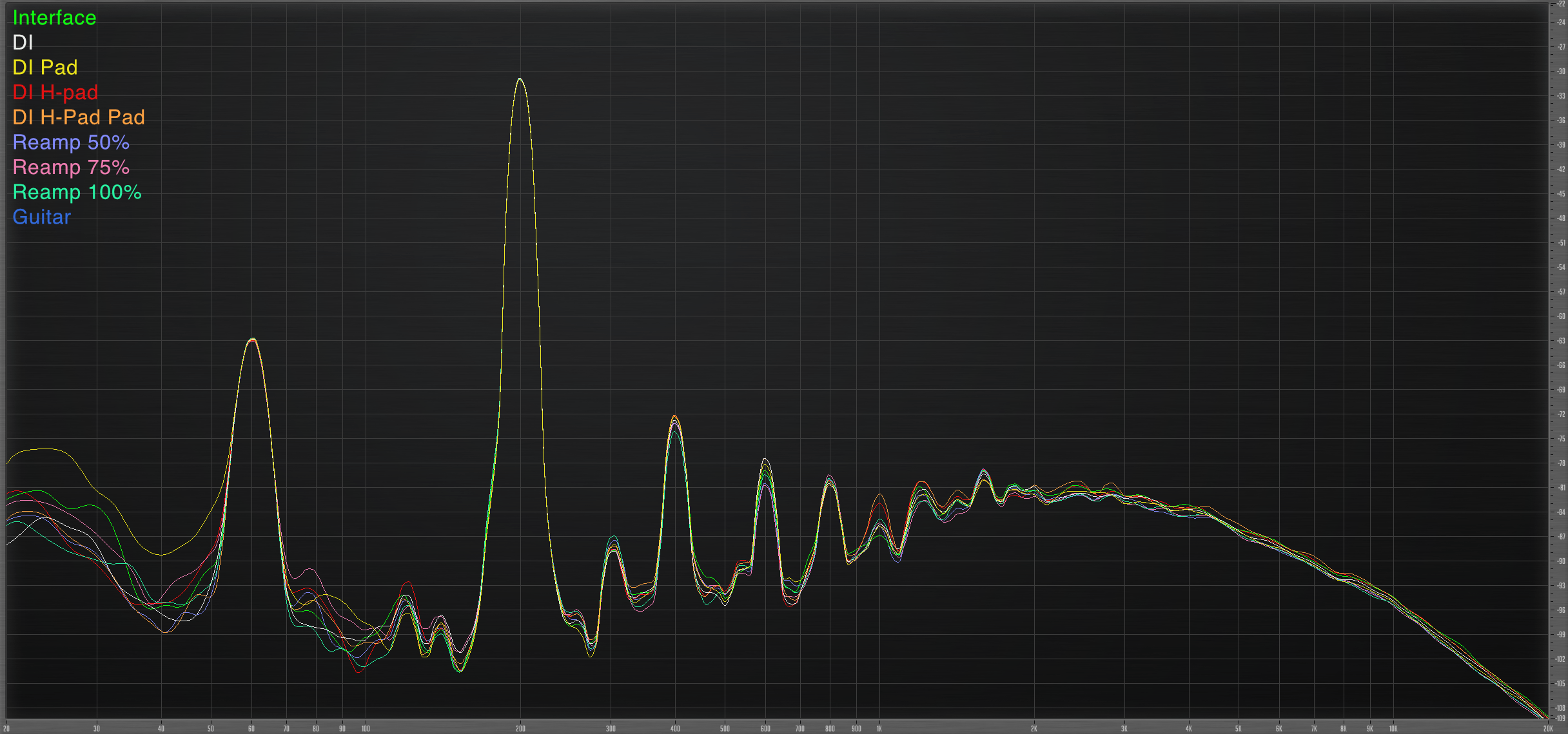
Distortion Part Deux
This time I’m using my trusty Tele-Gen signal generator.
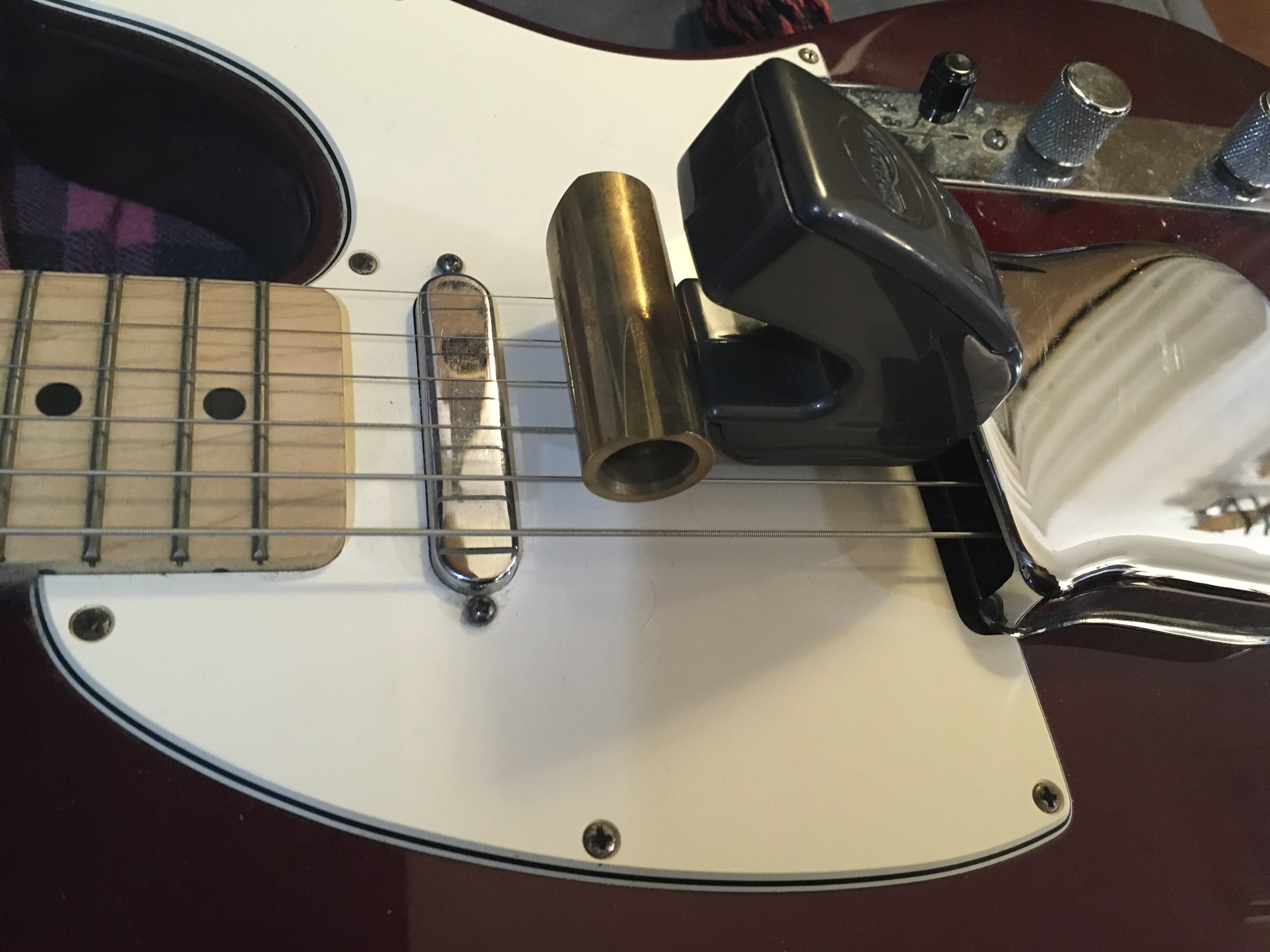
I took a Telecaster with an ashtray, a brass rock slide and an EBow.
I placed the EBow against the ashtray cover, and the slide against the EBow. This gave me a repeatable setup to make a ~977hz test signal straight out of a guitar.
Thusly we now have a reference signal of a real guitar. I took the signal response of the live guitar and simultaneously recorded it. I noted the SPL in the room when the guitar was playing live and matched all playbacks to that level via digital level adjustments. This ensures that the input to the amp is at a similar-ish level.
So this is the same test but with a real guitar signal as reference.
Discussion
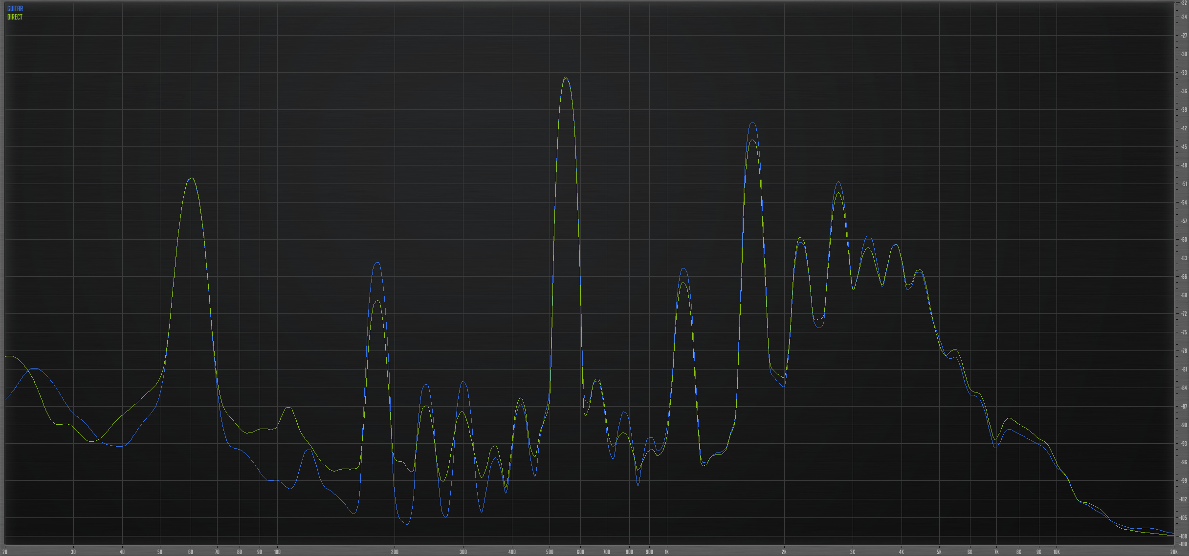
Since we have a reference this time, I thought I’d show the “Winner”. Going direct from the interface to the amp provided the most similar distortion characteristics.
This isn’t the whole story though. It entirely possible that with this specific signal at this specific level, I somehow hit a point in this very complex interaction where the Interface won.
If I were being paid to do these tests, I’d run at least another 40-50 runs of each signal at varying levels with varying frequency input to see if there’s non-linear differences (level affecting the “match”) or if a particular part of the spectrum is more sensitive.
That said… I’m not being paid well enough to do that. If someone wants to throw me the $3,500 or so for my time then I’d gladly do a comprehensive set of tests with a more robust procedure.
I did ‘play with it’ though. Informally I tried a few setups and it was fairly clear the Interface direct output gave the most similar distortion characteristics. Unfortunately you’ll have to trust me on that (or don’t, you shouldn’t!)
The real takeaway here is that none of these were particularly similar to the guitar. Not even the Interface output was! Even though I was wearing hearing protection for all of these tests, there was a difference I could hear.
Real sounds
Bluesy
This part is designed to have a variation in dynamics with some chunky chords.
- Interface Output - -5.89dB
- Passive DI - -26.34dB
- Passive DI -15dB pad onboard - 0.0dB
- Passive DI with 270Ω/47Ω H-Pad cable - -7.30dB
- Passive DI -15dB pad onboard with 270Ω/47Ω H-Pad cable - -5.82dB (began to clip, level too low!)
- Reamp 50% - +8.69dB
- Reamp 75% - -4.97dB
- Reamp 100% - -7.94dB
Jazz
The signal is fed into the ‘Low” input on the amp, and has a subtle fadeout to let you hear any noise floor increase.
- Interface Output - -8.92dB
- Passive DI - -29.8dB
- Passive DI -15dB pad onboard - -2.65dB
- Passive DI with 270Ω/47Ω H-Pad cable - -6.88dB
- Passive DI -15dB pad onboard with 270Ω/47Ω H-Pad cable - +12.00dB (began to clip, level too low!)
- Reamp 50% - +5.82dB
- Reamp 75% - -8.64dB
- Reamp 100% - -11.06dB
Rock
Single coils in the old school rock way. This is run through a boost pedal (Keeley Time machine Boost set to Modern at about 45%).
This should give you an idea of how the various methods work with extra non-linear behaviour and a pedal.
- Interface Output - -15.87dB
- Passive DI - -33.39dB
- Passive DI -15dB pad onboard - -3.24dB
- Passive DI with 270Ω/47Ω H-Pad cable - -15.48dB
- Passive DI -15dB pad onboard with 270Ω/47Ω H-Pad cable - +1.94dB (began to clip, level too low!)
- Reamp 50% - -0.0dB
- Reamp 75% - -11.74dB
- Reamp 100% - -19.65dB
Video
Hey, check out this video with me playing these parts instead? (Subscribe! It helps me a lot. Or don’t, you’re your own person.)
H-Pad
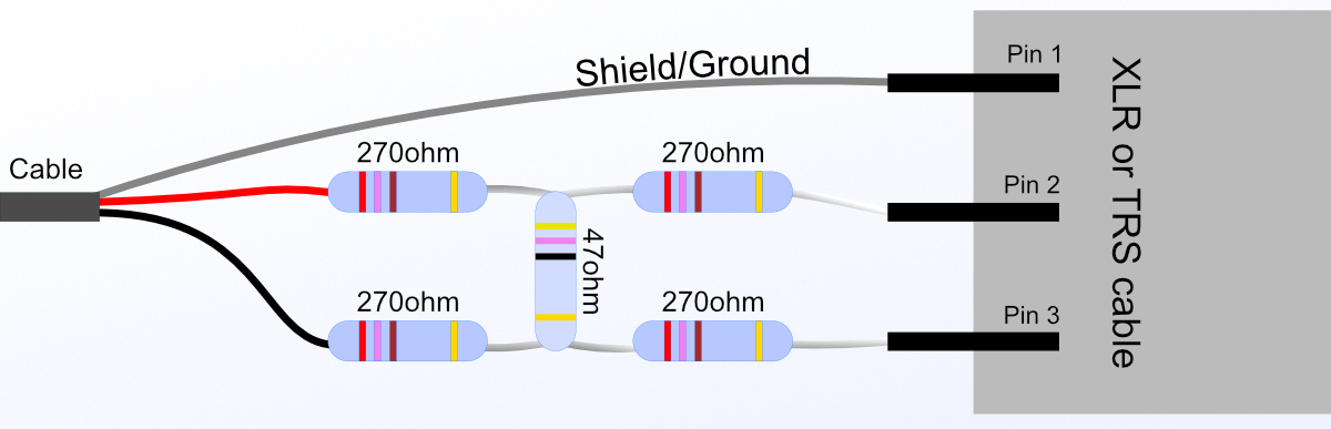
An H-pad is a type of resistor network that allows you to attenuate a balanced signal relatively easily.
For this application an H-pad with the resistor values shown above gives us a fairly decent level. I ran a circuit simulation assuming 600Ω on both sides, which is common for line level signals, and these resistor values give an attenuation of about 25.789dB.
Before we discussed that we need about 34dB of attenuation. If you used 4 300Ω resistors and a single 24Ω bridge that would get you almost perfect. I just didn’t have those values on hand. I certainly could have cobbled something together to get close, but with what I have that would have meant packing at least eight resistors into the XLR plug body. No thank you.
IMPORTANT It is important to know that this goes on the cable that is between your interface and your passive direct box. If you want to run it between the passive direct box and amplifier, then you need to use a T pad.
Just Google for “T-pad calculator” or “H-pad calculator” and you will find a number of calculators to give you the resistor values necessary for the attenuation that you want. In our case we want around 30-35dB of attenuation. That assumes that you liked the h-pad results.
How do I do this?
Here’s what you need to ‘reamp’ and get darn close with any setup you have.
- SPL Meter
- Some way to get a good guitar signal into your computer (DI box, instrument input, etc…)
- (Optional) - A splitter. Most DI boxes will have a ‘thru’
- If you do not have a splitter, you need an SPL meter. Many smart phones have apps that can do this.
- The necessary cables for the method you pick.
- Meter plugin for your DAW (dpMeter 3 is free and awesome)
With these instructions I am assuming that your goal is to have a sound that is somewhat close to how it would’ve sounded when playing directly through the amplifier.
I will give two types of directions: ones that assume you have a splitter, and directions if you do not have a splitter.
Splitter
The idea here is to record both the direct guitar and and amplified guitar signal, then match your re-amped signal level to the original amplifier recording. This is done entirely in the DAW.
SETUP
- Record the direct signal and simultaneously record a mic’d version from the amp.
- Place some sort of meter plug-in on the recorded amp version in your DAW
- Press play in your DAW and note the peak level and the integrated RMS (this is a level measurement, dpMeter 3 has it) of the recorded amplifier signal.
REAMP STAGE
- Create a new track that takes input from a microphone accepting sound from an amplifier.
- Input monitoring must be on!
- Set up your direct signal output to your amplifier.
- Press play in your DAW
- Adjust the level of your output track until the input track’s (from the amp) meters match the levels you found when testing the recorded live amp.
- Press record!
If you did this correctly than the levels of your original recording and your reading and recording will be identical, and they will sound very similar.
No Splitter
This method is similar but it requires that you have an SPL meter.
- Record the direct signal.
REAMP STAGE
- Set up the amplifier for recording.
- Plug-in a guitar and play something similar to the part that you will be recording.
- Use your SPL meter to note the level of sound in the room.
- Create a new track that takes input from a microphone accepting sound from an amplifier.
- Set up your direct signal output to your amplifier.
- Adjust the level of the output track so that the amplifiers SPL and overall sound is similar to when you played through the app.
- Press record!
If you did this correctly than the levels of your original recording and your reading and recording will be identical, and they will sound very similar.
Conclusion
It is pretty clear that all of the myths surrounding reamping are pretty nonsensical. The only thing I found was that you most certainly do not want to use a passive direct box in reverse by itself. The noise level will be somewhat high.
All of the other methods (except H-pad + DI box pad) produced acceptable sounds when calibrated properly. Not only that but simply using an interface output was more than sufficient and gives you a great deal of flexibility without requiring an investment.
I do believe that using the Reamp made it slightly easier to reproduce in authentic tone, but it most certainly was not the only way and it still required some calibration.
Hopefully I have given you an understanding of the process so that you can make your own decisions and have at least a basic understanding of what is necessary to get a decent sound. I make no claim to any of these methods being ideal, I simply wish to show you what is possible and to provide the technical information about the process.
Best of luck out there!
Support Me!
This post took 53 hours to research, photograph, write and edit. If you appreciate the information presented then please consider joining patreon or paying me for my time spent bringing you quality content!