This is the first part of DAW v DAW 7.2. If you haven’t read part 1, then I encourage you to do so.
In this article I’ll be:
- Explaining what is being tested
- Explaining why this is a multi-part article.
- Discussing the test procedure.
- Requesting feedback
Other parts in this series:
- Daw v Daw 7.2 update, again...
- Pro Tools
- FLStudio
- Live
- Bitwig
- Mixbus
- Ardour
- DP
- Logic
- Reaper
- Waveform
- Cubase
- Studio One
- Conclusions
Contents
- What is being tested
- What is NOT being tested
- Why multiple parts?
- Test Procedure
- Example
- Conclusion
- Meta
What is being tested
I’m testing the MIDI input to Audio output latency of various DAWs to see how far the latency deviates from what’s reported, and if the latency is consistent from input to input.
The exact values may not correlate to your device. A 64 sample buffer on one model of an interface may not produce the same latency as a 64 sample buffer an another model. It can vary from driver version, hardware revision, OS version, etc…
I’ll be using a single device for all these tests, so it is not possible to determine if a DAW is adding extra buffers or if the device is. The “jitter” from input to input is usually not device specific.
You can take away 2 things from these tests:
- Which DAWs have more/less latency than others, but not the exact amounts (unless I tested many interfaces).
- Which DAWs produce identical delay between every MIDI->Audio transformation.
What is NOT being tested
- The total Jitter - Most tests will only have 3-5 frames. This is not enough to determine the exact number of buffers or amount of jitter, only its existence and a guess.
- Audio Jitter.
- MIDI->MIDI Jitter (even though this does exist in most DAWs with MIDI->Audio Jitter)
- “Sound Quality”
Why multiple parts?
I’ve been working on this for the last 3 weeks. In fact, I leaked a template for the article on accident :) (with no data filled in).
The procedure I was using was as follows:
- Record the signal on the scope
- Take screenshot of scope.
- Note measurements of scope.
- Record measurements of scope.
- Record reported data from DAW (latency, settings).
After doing 50+ measurements, which took me 15 minutes each, I realized the following problems:
- Scope images were difficult to read.
- Scope measurements were not accurate. The exact same input would yield measurements that were +/-5%, which is a problem when you’re trying to gauge variance or deviation!
- I setup the test incorrectly in some cases.
- The process was laborious - multiple opportunities for error, and exceptionally monotonous.
- Manually set trigger.
- Manually trigger data.
- Manually save data to generically named CSV.
- Manually save data to generically named png.
- Manually transfer data via USB flash drive.
- Manually rename files.
- Manually transfer measurements from image or csv to spreadsheet.
I spent around 50 hours troubleshooting process errors in steps, reconsidering what needed to be measured, fine tuning the measurement devices and giving up and writing my own software for visualization/measurements.
Even worse still, I realized that some DAWs had a setting or another that affected the results, and often I wasn’t using the default settings. So I would have to go back and redo all of the tests and take note of specific settings.
So here I am now. The test procedure below is less error prone, faster and not as annoying for me to execute. Despite the improvements, I’d like to present this first before I get on doing 100s of tedious measurements.
Test Procedure
Hardware
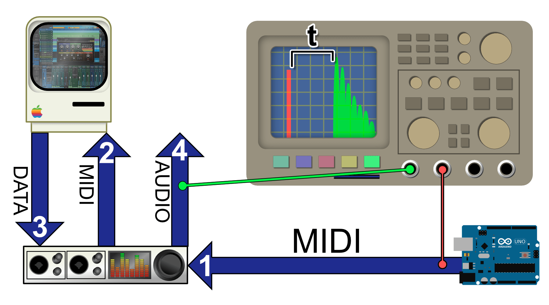
The flow is shown in the image above.
- Microcontroller sending MIDI out to an Audio Interface.
- DAW taking MIDI from Audio Interface.
- DAW sending the MIDI to a Sampler.
- The sampler uses MIDI to trigger a 3 sample impulse.
- The sample is 1 sample of maximum sample value, and 2 samples of 0.
- The DAW sends audio out from the sampler to the Audio Interface.
- A cable is inserted to the Audio Interface.
- An Oscilloscope taps the signal between the Microcontroller and the Audio Interface to capture the binary MIDI.
- An Oscilloscope taps the signal at the Audio Interface output (Tip of the TRS output).
Why don’t I just do a loopback test?
Most DAWs have automatic recording compensation. It takes time for the audio to reach the DAW, and the DAW has some sort of idea (asks the interface drivers) of what it thinks that latency is, and the DAW then moves the audio back in time by that amount.
The problem is that the reported value from the interface driver might be incorrect. The audio’s position in the timeline would be compensated, but by an incorrect amount. My measurements would include this error with no way of quantifying it.
It would show any “Jitter”, but it would make measuring the absolute MIDI->Audio latency inaccurate. I’m interested in “Jitter” and the total latency. The only way to capture that is to capture the MIDI signal at the source, and the actual audio output at the source.
Setup
Tests are at 48,000hz sampling rate, using a Komplete Audio 6. I chose to use a common USB interface to emulate the most likely common use. This hardware and sample rate will be used in every test.
All tests are in macOS 10.15.7. If there is significant interest in testing DAWs in Windows then I will. (i.e. You pay for my time to suffer through Windows.)
Software
I’m using EasyScope in a Windows Virtual Machine to control a Siglent 1204x-e.
The scope is set to single trigger on +100mv on Channel 1 (MIDI out from microcontroller). Once the capture occurs, I export to CSV.
I have some code that finds:
- Signal onset time - first time the signal violates a threshold.
- Signal outset time - first time the signal goes below the threshold and stays there for n-samples.
- Delta between supplied times
And then graphs the result with appropriate labels.
Code
Code is here. Don’t expect anything particularly cool (or even good).
I wrote this Sunday Oct 25 (today?) in a couple hours, so I’ll probably be refining it and wondering what idiot wrote this line of… oh.
Example
5 measurements as shown.
I’m working on getting that jumpiness out of the animation.
How to Read the Chart
- Orange (multiple pulses) - MIDI signal.
- Blue (spike) - Audio signal.
- Bottom bar - Marks the delay between the signals.
Y axis on the top chart is amplitude. X axis is samples *OF THE OSCILLOSCOPE, not the audio device!
The label below the bottom chart correctly lists the samples of delay of the audio device.
Conclusion
I’ll be publishing this article and waiting a few days before I begin measurements. I’ll be posting articles one DAW at a time.
Just this write up has made me realize there’s a few things I need to adjust.
Meta
This post took:
- 35 hours to realize everything I’ve done thusfar was incorrect.
- 12 hours to think about a better way to do things.
- 9 hours to execute and test my new ideas.